Wireless Data
CMX7164 – Multi-mode Wireless Data Modem
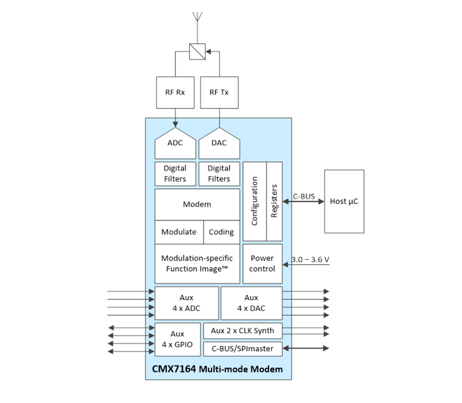
The CMX7164 Multi-mode Wireless Data Modem is a half-duplex device supporting 4/16/32/64 QAM, 2/4/8/16 FSK, GMSK/GFSK and V.23 modes in multiple channel spacings, under host control.
An integrated analogue interface supports direct connection to zero IF I/Q radio transceivers with few external components; no external codecs are required.
Intelligent auxiliary ADC, DAC and GPIO sub-systems perform valuable functions and minimise host interaction and host I/O resources. Two synthesised system clock generators develop clock signals for off-chip use.
The C-BUS/SPI master interface expands host C-BUS/SPI ports to control external devices.
The device utilises FirmASIC component technology. On-chip sub-systems are configured by a Function Image data file that defines the device’s function and feature set. Four Function Images are available:
- CMX7164 FI-1.x GMSK/GFSK Modem
- CMX7164 FI-2.x 2/4/8/16 FSK Modem
- CMX7164 FI-4.x 4/16/32/64 QAM Modem
- CMX7164 FI-6.x V.23 Modem
See the Downloads section below.
The differential inputs are ideal for direct connection to RF Building Block ICs such as CMX994, CMX994A, CMX994E RF Direct Conversion Receiver ICs
For systems requiring support for wider 50kHz channel bandwidths and higher data rates up to 40k symbols per second CML recommends the CMX7364 Multi-mode High Performance Wireless Data Modem.
Devices are available through our Distributor Network.
Features
- GMSK, GFSK FI-1.x
- 2-FSK, 4-FSK, 8-FSK, 16-FSK F12.x
- 4-QAM, 16-QAM, 32-QAM, 64-QAM FI4.x
- V.23 FI6.x
- Two Frame-Sync Detectors
- Automatic Frame Sync Detect
- Rx Crrier Fequency Correction
- Receive Signal Quality Measurement
- Over-air Compatible with Standard Modems
- Robust Data Packet Modes
- C-BUS Host Serial Interface:
- SPI-like with Register Addressing
- Read/Write 128-Byte FIFOs/Data Buffers
- Master C-BUS/SPI Serial Interface:
- For External Slave Devices
- Pass-through Mode
- High Performance I/Q Radio Analogue Interface:
- Tx and Rx: ‘Direct Connect’ to Zero IF Transceiver
- Simple External RC Filters
- Configurable Rx and Tx Pulse Shaping Filters
- Reconfigurable Digital Rx IF Filter
- Deviation Control without Manual Trim
- Auxiliary Functions:
- Four 10-bit DACs and Four 10-bit ADCs
- Autonomous RAMDAC Sequencer
- Automatic Support For DC Calibration of CMX998
- ADC Averaging and Trip on High/Low ‘Watch Modes’
- Four GPIO: Sequence GPIO on Rx or Tx Trigger
- Start Tx on Digital Trigger Input
- Automatic Gain Control
Applications
- High Performance Narrow-band Radio
- For 6.25kHz to 25kHz RF Channel Spacing
- Telemetry, SCADA and Data Modem Systems
- Digital Software Defined Radio (SDR)
- High-speed Wireless Data
- FCC Part 90: New Spectral Efficiency Requirements
- Mobile Data over Fading Channels
Power Supply Requirement
- 3.0 to 3.6 V
Design Resources
Function Images
- GMSK/GFSK modulations (Function Image 7164FI-1.x) – with BT=0.5, 0.3, 0.27 or 0.25 and up to 20kbps. The GMSK packet data is over-air compatible with the FX/MX909B and the CMX7143 (Function Image 7143FI-1.x)
- 2-FSK, 4-FSK, 8-FSK and 16-FSK modulations (Function Image 7164FI-2.x) – with root raised cosine filtered with α=0.2 with optional sinc filtering, supporting up to 40 kbps in a 25kHz channel. Flexible bit rates support a wide range of applications requiring a selectable bit rate and robustness.The 4-FSK data is over-air compatible with the FX/MX919B and the (CMX)7143FI-2.x
- 4-QAM, 16-QAM, 32-QAM and 64-QAM modulations (Function Image 7164FI-4.x) – are root raised cosine filtered with α=0.2, 0.35 or a user programmable filter. The 7164FI 4.x supports up to 96kbps in a 25kHz channel, with channel estimation and equalization to provide robust performance under realistic channel conditions. For greater flexibility, different rate FEC modes are provided. Receive signal quality measurement is supported, making a useful assessment of link conditions.Adaptive Coded Modulation (ACM) features allow modulation type and block format to be changed on the fly via over-air commands that control a receiving CMX7164. They enable a Tx host to select optimum modulation and coding per burst to suit application message size, link channel quality and can also relax required Rx host message parsing speed.
- V.23 Modem – Function Image 7164FI-6.x The V.23 modem enables communication with legacy telecom systems. The implementation supports 1200 baud 1 to 8 byte data blocks with start bit, stop bit and parity generation in transmit and start bit, stop bit and parity checking and removal in receive.
CMX7164 FAQ
Q. Should pull-up or pull-down resistors be connected to CMX7164 device GPIO pins (GPIOA, GPIOB, GPIOC, and GPIOD)?
A. The CMX7164 features flexible GPIO pins that can be independently configured via C-BUS serial interface commands to operate in one of the following modes: CMOS digital output, CMOS digital input or CMOS digital input with bus hold. Bus hold automatically engages a 75kohm internal pull-up or pull-down resistor that reinforces the current logic state of the input signal. As is normally the case, the state of a CMOS digital input will be indeterminate and may increase device supply current when the input’s voltage is not at valid ‘0’ or ‘1’, i.e. when the node voltage is “floating.”
When the CMX7164 is RESET (by asserting its RESETN pin, issuing a C-BUS General RESET or by triggering an internal power on reset) all its GPIO pins are immediately placed in CMOS digital input mode. Any GPIO pins not being pulled either up or down by an external load will be floating. Once a Function Image™ is loaded into the device then all its GPIO pins are placed in CMOS digital input with bus hold.
If user circuits require one or more GPIO pins to be held at a deterministic ’0’ or ‘1’, i.e. not floating after RESET and before the Function Image™ is loaded then that circuit should connect external pull-up or pull-down circuits to such pins.
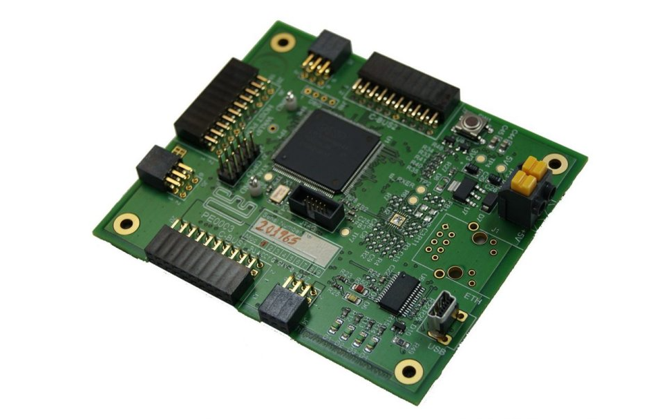
PE0003 |
The PE0003 Evaluation Kit Interface Card is a global interface system for use with evaluation kits for CML’s new generation ICs, including FirmASIC™ based products. This greatly simplifies the approach to the evaluation and design-in process. | Link to:
|
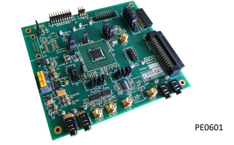
PE0601-7164
|
The PE0601 Platform Evaluation Kit is designed to assist in the evaluation and application development of the CMX7x6x range of FirmASIC products.
Documents
|
FAQs |
ScriptsCMX7164 2FSK 4FSK RAW Scripts The two scripts contained in the ZIP file demonstrate the use of 2/4FSK transmitting and receiving up to 7 million bits of raw data through an RF wireless link. These scripts require the following evaluation boards: Two x PE0003, Two x PE0601-7164, One x EV9980, One x EV9920B. It is important to read the included readme.txt file. It is recommended that you read the QAM + RF Demonstration application information and watch the YouTube video for the Full QAM + RF Demo” as the setup of the evaluation boards is the same PE0601-7164 – 2FSK 4FSK Formatted Scripts – Download The two scripts contained in the ZIP file demonstrate the use of 2/4FSK transmitting and receiving Block 2 Formatted data through an RF wireless link. The Data frame consists of Header Block, Intermediate Block and Last Block. These scripts can be easily modified to support other Block Types. These scripts require the following evaluation boards: Two x PE0003, Two x PE0601-7164, One x EV9980, One x EV9920B. It is important to read the included readme.txt file. It is recommended that you read the QAM + RF Demonstration application information and watch the YouTube video for the Full QAM + RF Demo” as the setup of the evaluation boards is the same. CMX7163/64 – QAM Constellation Diagram Support –Download Support Video – View The seven scripts contained in the zip file allow viewing of QAM constellation diagrams in the CMX7163 or CMX7164. These scripts are used in the YouTube video, “QAM Constellation Diagrams Discussion” which can be found on the Videos tab on this page. The following Evaluation Kits are required; PE0601-7163 or PE0601-7164, PE0003, EV9980 and EV9920B. GMSK data transfer using the CMX993, CMX7164 and CMX994 – Download Two scripts that exchange raw 9600baud GMSK messages transmitted by the CMX993 and received by the CMX994. |
||
Knowledge BasePE0601-7163/7164 Board Schematics. Version B03 – Download EF0601-M25P10-10-7164.h – Thick Stub – Download C-BUS guide to operation and interfacing – Download |


