Digital/Analogue Two-Way Radio Products
CMX7241/CMX7341 – Advanced PMR/LMR Digital Common Platform Processors
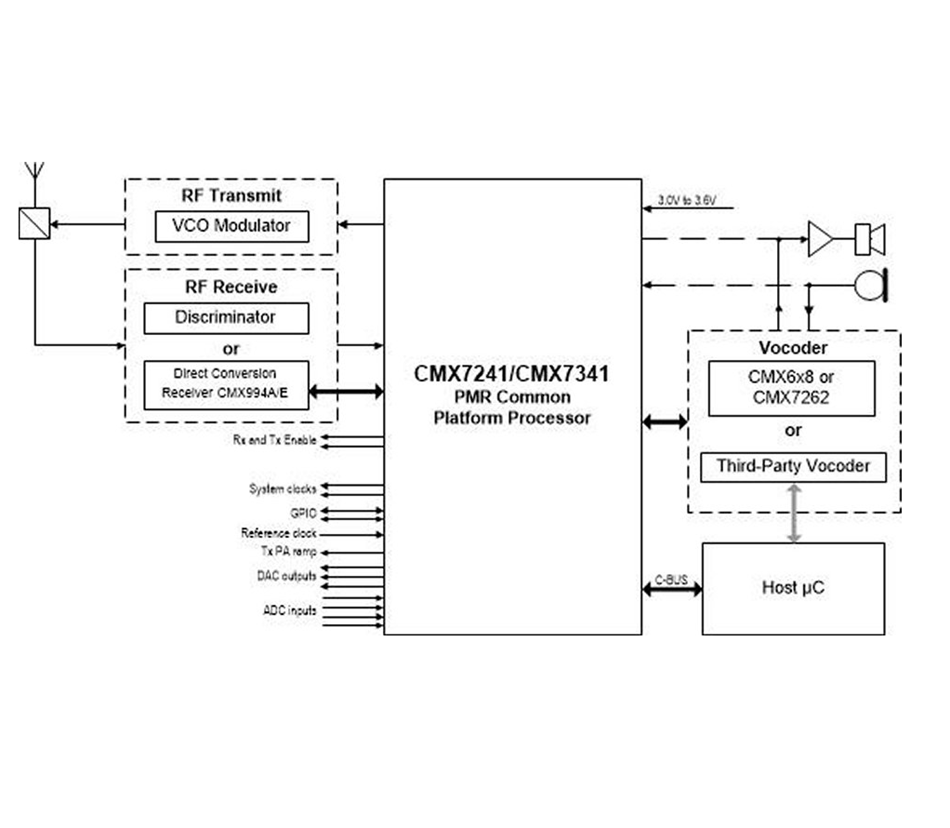
The CMX7241/CMX7341 provides a common platform to support digital and analogue FDMA and 2-slot TDMA PMR/LMR.
Based on CML’s FirmASIC® component technology, a Function Image™ (FI) upload determines the CMX7241/CMX7341 overall function and operating characteristics. The CMX7241 and CMX7341 provide the same system functionality and can accept the same FI but are targeted at different system implementations:
- CMX7241 is pin compatible with the CMX7141 enabling a smooth forward evolution
- CMX7341 has a differential I/Q Rx interface for optimum performance and direct connection to CML’s CMX994A/E Direct Conversion Receiver ( DCRx) ICs
The combination of CMX7341 and CMX994A/E ICs enables a small, low cost, low power consumption multi-standard PMR/LMR system to be realised.
Four Function Images are available, these can be downloaded from the CML Technical Portal (contact for access):
- CMX7241/7341 FI-1.x – dPMR™ and Analogue PMR Processor with Rx I/Q Support
- CMX7241/7341 FI-2.x – DMR Air Interface Processor
- CMX7241/7341 FI-3.x – NXDN, ARIB STD-T98/T102 and Analogue PMR Processor
- CMX7241/7341 FI-4.x – APCO P25 and Analogue PMR Processor
Click the links above or visit the "Downloads" section of this page to download the datasheets for each individual Function Image.
Devices are available through our Distributor Network.
Features
- Common Platform Processors
- Analogue/Digital PMR/LMR
- FDMA and 2-slot TDMA
- Complete voice and data processing
- Advanced features
– Embedded Air Interface
– Tx sequencer
– Minimal host interaction
– Autonomous CMX994A/E control
– Audio codec for vocoder support - Multi-standard Function Images all with analogue PMR support
– DMR, dPMR™, NXDN™, ARIB STD-T98, ARIB STD-T102, APCO P25 - Auxiliary features
– 2 x ADCs (4 mux inputs)
– 4 x DACs
– GPIO
– System clocks - General features
– I/Q and LD Rx support
– Low power 3.3V operation
– C-BUS serial interface
– Small VQFN/LQFP packaging
Applications
- Multi-mode Analogue/Digital radio
- FDMA/2-slot TDMA systems
- Portable radios
- Mobile radios
- Base station/repeaters
Power Supply Requirement
- 3.0 to 3.6 V
Design Resources
Function Images
dPMR™ Air Interface + Analogue PMR/LMR – Function Image™ 7241/7341FI-1.x
- Automatic digital/analogue call detection
- dPMR™ – ETSI TS 102 490, TS 102 658 Mode 1/2/3 compliant
- Analogue PMR/LMR – EN 300 08, EN 300 296 and TIA-603-D compliant
- Rx I/Q and LD support (CMX7341 includes differential inputs)
- Direct connection to autonomous control of CMX994A/E DCRx IC
- Codec support for RALCWI®, AMBE+2™, TWELP® Vocoders
DMR Air Interface + Analogue PMR/LMR – Function Image™ 7241/7341FI-2.x
- DMR ETSI TS 102 631 Tier 1/2/3 compliant
- Analogue PMR/LMR – EN 300 08, EN 300 296 and TIA-603-D compliant
- Rx I/Q and LD support (CMX7341 includes differential inputs)
- Direct connection to autonomous control of CMX994A/E DCRx IC
- Codec support for AMBE+2™ vocoder
NXDN + ARIB STD-T98/102 + Analogue PMR – Function Image™ 7241/7341FI-3.x
- Auto detect of Digital/Analogue PMR
- Analogue PMR
- Digital PMR:
- NXDN conventional and class D trunking
- ARIB STD-T98 (DCR)
- ARIB STD-T102
- Tx sequencer
APCO P25 + Analogue PMR – Function Image™ 7241/7341FI-4.x
- Auto detect of Digital/Analogue PMR
- Analogue PMR – EN 300 08, EN 300 296 and TIA-603-D compliant
- Digital PMR – APCO P25
- Tx sequencer
Function Image™ Roadmap includes:
- PDT Air Interface
Other features include: two auxiliary ADCs with four selectable inputs, four auxiliary DAC interfaces (with an optional RAMDAC on the first DAC output, to facilitate transmitter power ramping), GPIO and System Clock possibilities.
The devices have flexible powersaving modes and are available in the following packages: VQFN (CMX7241 and CMX7341) and LQFP (CMX7241 only).
Q: When using the CMX7341 I/Q AGC functionality, the currently used I/Q AGC step is reported back in the Aux 1 Data and Status Register ($A9). How do these steps relate to the current actual gain settings within the CMX994A/CMX994E and CMX7341 devices?
A: The gain adjustment steps are automatically controlled by the CMX7341 when I/Q AGC is enabled. When setting the optimal I/Q input signal level the CMX7341 will adjust its analogue input gain stage and LNA/VGA gain stages of the CMX994A/CMX994E. The reported step gain breakdown is as follows:
| AGC Steps | CMX994AE LNA Gain dB | CMX994AE VGA Gain dB | CMX7341 Input Gain dB | Total Gain dB |
|---|---|---|---|---|
| 8 | 0 | 0 | 19.2 | 19.2 |
| 7 | 0 | 0 | 12.8 | 12.4 |
| 6 | 0 | 0 | 6.4 | 6.4 |
| 5 | 0 | 0 | 0 | 0 |
| 4 | -12 | 0 | 0 | -12 |
| 3 | -18 | -6 | 0 | -24 |
| 2 | -18 | -18 | 0 | -36 |
| 1 | -18 | -30 | 0 | -48 |
| 0 | -18 | -42 | 0 | -60 |
This FAQ is applicable to Function Images 7341-1, 3 and 4.
Analogue PMR voice operation
A pair of scripts to realise analogue PMR voice transmission. Requires 2 x PE0403-734x Evaluation kits and 2 x PE0003 Controller kits.
7241/7341FI-1.1.x.x Configuration Guide
This Configuration Guide is intended to illustrate the signal routing through the CMX7241 and CMX7341 as a visual aid to configuring the device for each specific operation. It is currently specific to Function ImagesTM 7241/7341FI-1.1.x.x but will be largely suitable for later revisions. The Configuration Guide is not intended to cover all of the hardware, functions or possible set-up modes. It is a virtual representation of the device and does not reflect the true architecture.
| PE0003
|
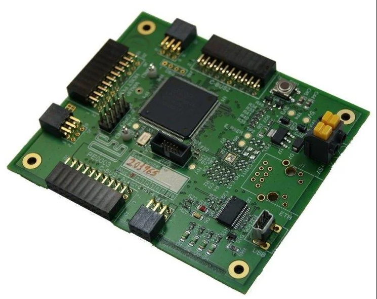
The PE0003 Evaluation Kit Interface Card is a global interface system for use with evaluation kits for CML’s new generation ICs, including FirmASIC™ based products. This greatly simplifies the approach to the evaluation and design-in process.
Documents |
| PE0403
|
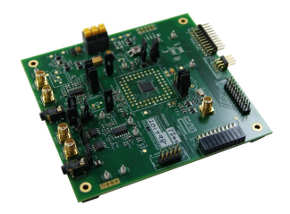
The PE0403 Platform Evaluation Kit is designed to assist in the evaluation and application development of the CMX724x and CMX734x ranges of FirmASIC® products.
Documents |
Knowledge Base
PE0403 724x Board Schematics. – Download PE0403-734x Board Schematics. – Download PE0403-7241 PE0403-7341 Quick Start. A simple guide to help users get started evaluating with the PE0403-7241 and PE0403-7341. – Download PE0403-7341 Quick Start. A simple guide to help users get started evaluating the CMX7341 using a Direct Conversion Receiver, the CMX994E, as an analogue PMR receiver. Kits required: PE0403-7341, EV9942E and PE0003.- Download C-BUS Guides. Guides to operation and interfacing. – Download |


