Wireless Data
FX919B/MX919B – Half Duplex 4FSK Packet Data Modem
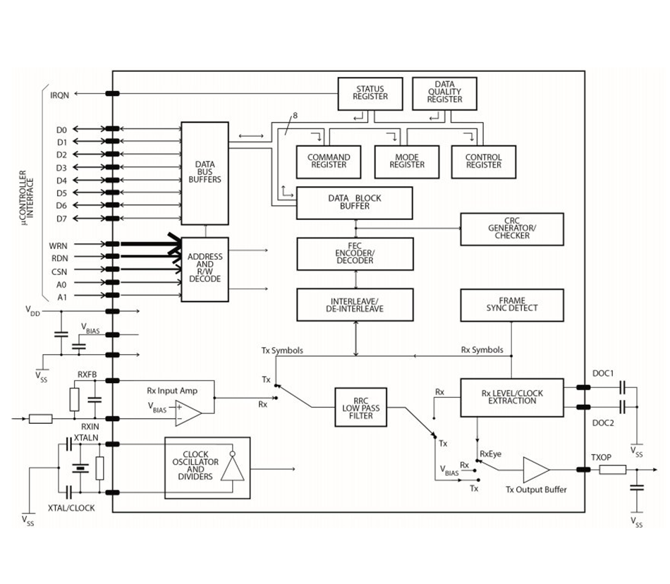
The FX919B/MX919B is a CMOS integrated circuit that contains all of the baseband signal processing and Medium Access Control (MAC) functions required for a high performance half-duplex 4FSK Wireless Packet Data Modem.
The circuit assembles application data received from the processor, adds forward error correction (FEC) and error detection (CRC) information and interleaves the result for burst-error protection.
In receive mode, the FX919B/MX919B performs the reverse function using the analogue baseband signals from the receiver discriminator.
The FX/MX919B uses data block sizes and FEC/CRC algorithms for applications which require high-speed transfer of data over narrow-band wireless links.
Devices are available through our Distributor Network.
Features
- 4FSK Modulation
- Half Duplex, 4.8kb/s to 19.2kb/s Operation
- Full Data Packet Framing
- Flexible Operation Modes Host Processor Interface
Applications
- High-Speed Packet Data
- Wireless Bar Code Readers
- Point-Of-Sale Terminals
Power Supply Requirement
- 3.0V – 5.5V
Design Resources
FX919A, MX919A and MX919B FAQ
Q. I am trying to decide whether to use the FX919B or FX929B 4LFSK wireless data pumps in my application, can you highlight the differences for me?
A. The main difference between these two devices is that the FX929B data pump is aimed at systems that follow the RD-LAP and RCR STD-47 over-air standards. The FX919B is more general purpose and allows a broader range of protocols to be met. The main formatting difference is that the FX929B provides a support for automatic Station ID processing.
Q. How much time elapses between the issuance of a RESET task and the subsequent setting of the BFREE bit?
A. The time required for the BFREE bit to be set in response to a RESET task will be no less than 3 bit times and no more than 6 bit times after the RESET task has been issued.
Q. My MX919B product works fine at 9600bps, but when I increase the data rate to 19.2kbps, the BER degrades badly. What is going on?
A. The problem is most likely to be the IF filter bandwidth.
When the 9600bps radio is receiving the preamble, the “symbol sync” pattern (“+3+3-3-3”) effectively has a 2400bps fundamental frequency component. When the preamble moves into the other data “packets” (frame sync, data), the higher frequency content of that data is still within the IF filter skirts and no phase distortion occurs: BER is acceptable.
When the 19.2kbps radio trains, its symbol sync has a 4800bps fundamental frequency component, and this likely passes through the IF filter with no problem.
However, if the 19.2kbps and 9600bps radios have the same IF filter bandwidth, the higher frequency content in the 19.2kbps data stream is likely bleeding over into the IF filter skirts.
This can cause phase distortion and will lead to incorrect decisions about incoming signal zero crossings. This will then lead to poorer BER.
Q. How do I view the “eye diagrams” for the MX919B and the MX929B?
A. A two-channel oscilloscope is needed for this testing.
One channel of the oscilloscope should be placed on the signal path of interest, such as the Tx output (after the external RC filter). If the Rx eye diagram is to be viewed, set the “RXEYE” bit in the Mode Register to “1” and connect the oscilloscope probe downstream of the external RC filter on the TXOUT pin.
(This Mode Register bit causes the MX919B & MX929B to enter a special test mode whereby the Rx output is placed on the TXOUT pin.
This mode is provided because observation of the direct discriminator output of a root raised cosine Tx filtered signal is not very recognizable and is generally not useful.)
The other oscilloscope channel should be used for triggering and should ideally be placed on the transmitting MX919B/MX929B /IRQ pin. This will allow the triggering to be synchronized with the completion of each transmitted data word. If this triggering location is not practical, use the receiving MX919B/MX929B’s /IRQ signal for triggering. The falling edge of the /IRQ line should be used for triggering. The data stream used for this testing should have a reasonably random structure.

